Drainage Behind Wall Structures
Wall Drainage
Subsurface drainage systems designed to provide a continuous drainage pathway behind retaining walls and below-ground wall structures
Water entering the ground behind retaining walls and below-ground structures can accumulate against the structure where an effective drainage pathway is not provided. This accumulation can contribute to hydrostatic pressure acting against the wall, making the management and controlled removal of water an important consideration in below-ground wall design.
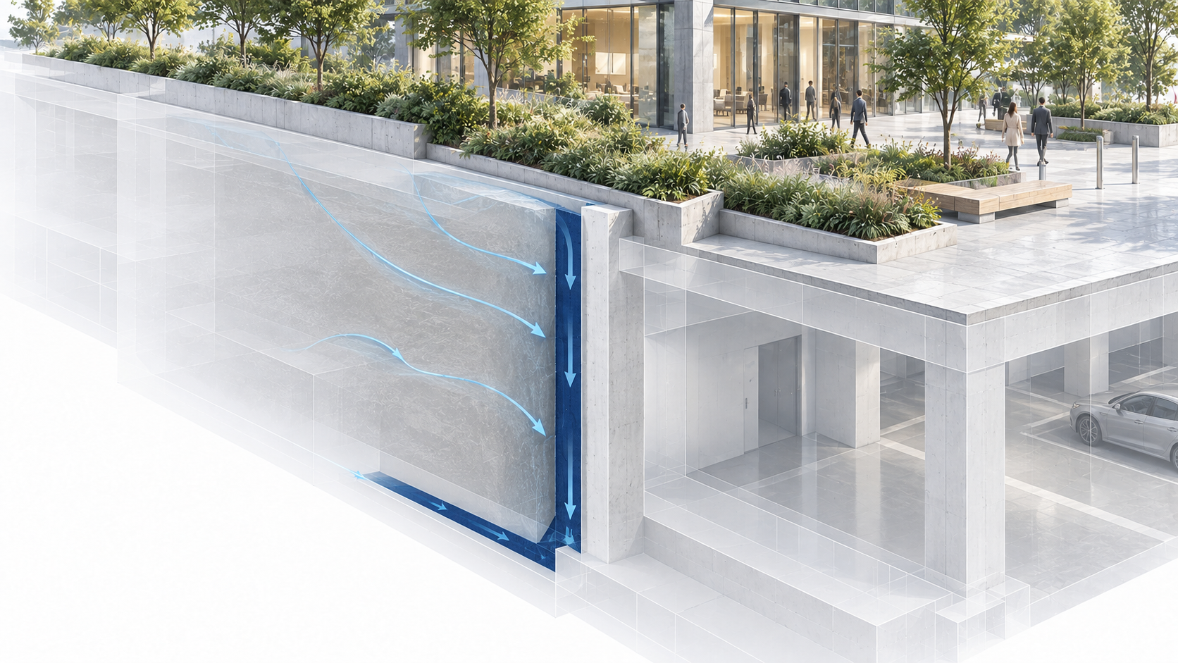
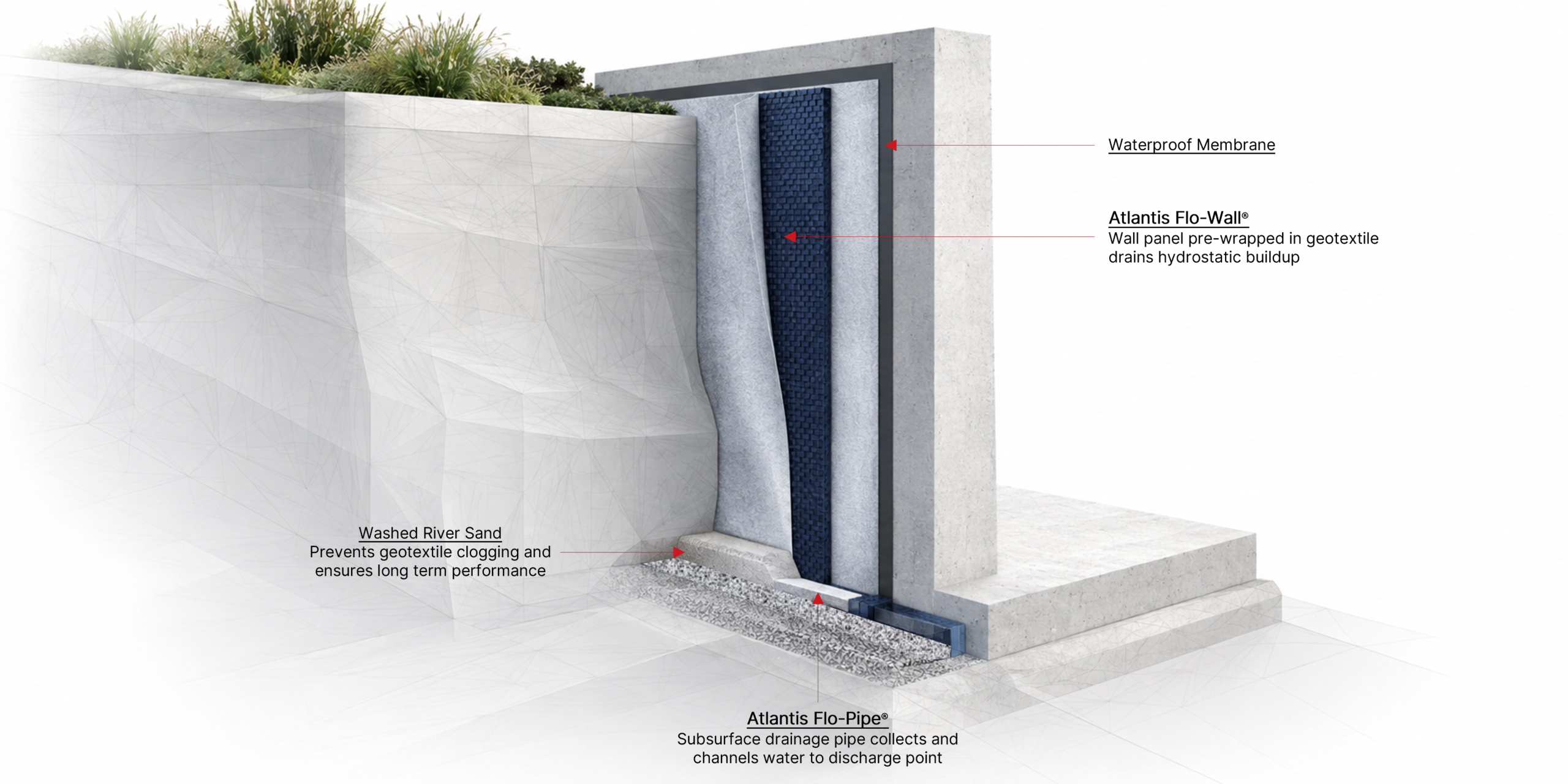
Atlantis wall drainage systems create a continuous vertical drainage pathway between the structure and the surrounding ground. The high-void drainage layer provides space for water to enter and move under gravity toward the designated collection and discharge system, helping limit the accumulation of water directly against the wall while maintaining a relatively thin drainage profile.
Maintaining a continuous drainage pathway is therefore critical to the performance of the wall drainage strategy. The drainage layer must remain hydraulically connected across the wall surface and provide an uninterrupted route toward the collection and discharge system below, allowing water to be managed behind the structure rather than accumulate against it.
How Vertical Wall Drainage Works
Drainage Principle
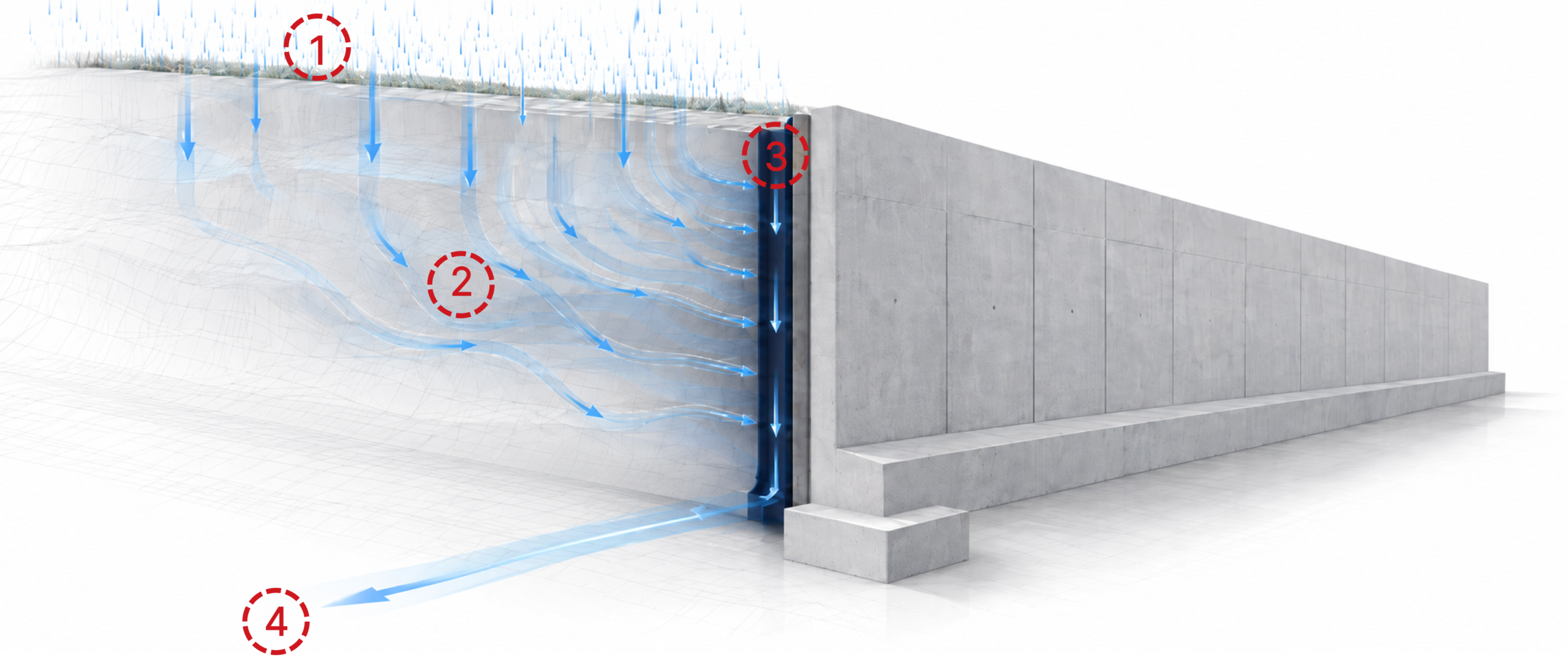
Rainfall and surface water can infiltrate into retained ground and migrate downward through the soil profile. As water moves through the ground, local hydraulic gradients can also direct moisture toward below-ground walls and retaining structures. Without an effective drainage pathway, water can accumulate adjacent to the wall and contribute to hydraulic head and hydrostatic pressure.
A vertical wall drainage system intercepts water approaching the structure and provides a continuous drainage pathway between the retained ground and the protected wall interface. Water is conveyed downward under gravity, collected at the base of the wall, and directed away from the structure toward the project’s designated drainage or discharge system.
Applications
Wall Drainage Across the Built Environment
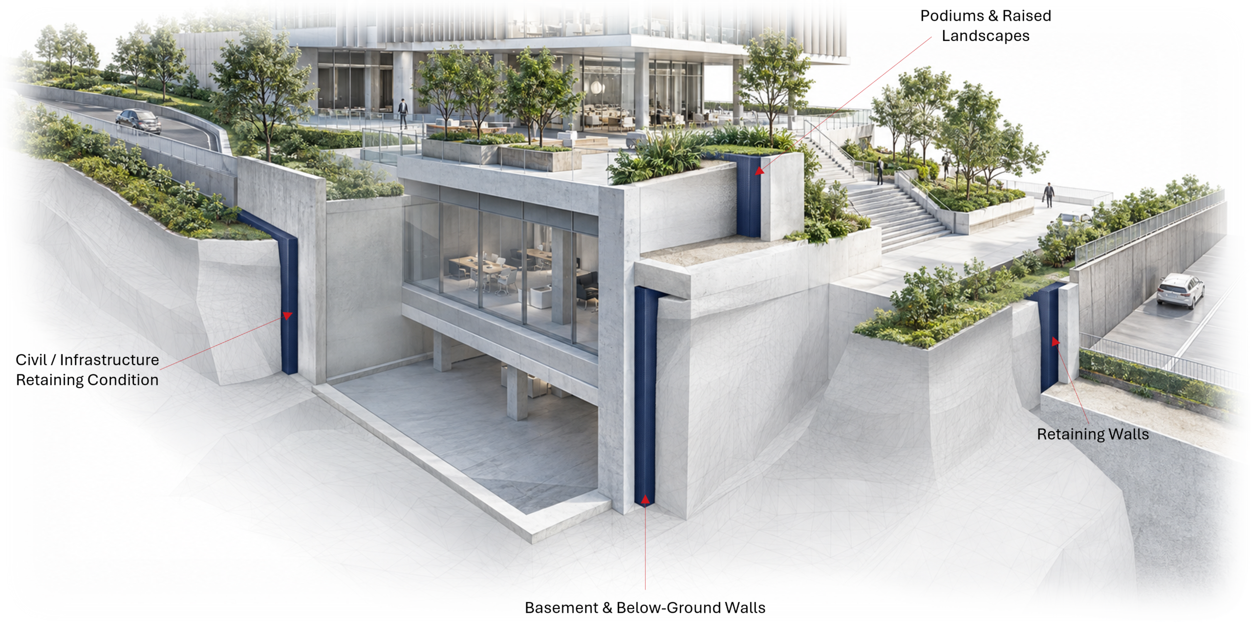
Vertical drainage can be integrated behind below-ground and earth-retaining structures where water within the surrounding ground requires a defined pathway to collection and discharge.
Flo-Wall® System
Purpose-Built for Wall Drainage
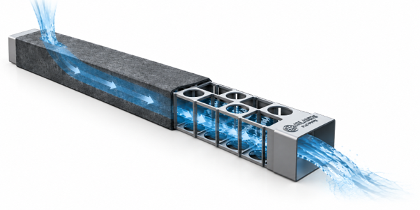
Atlantis Flo-Wall® is a pre-assembled vertical drainage system designed for installation behind retaining walls and below-ground structures. The system combines a modular drainage core with hydrophilic geotextile to create a continuous drainage pathway between the retained ground and the protected wall interface.
Supplied as a pre-assembled panel, Flo-Wall® integrates the drainage core and filtration layer into a single system, simplifying the formation of the vertical drainage zone while maintaining continuity across the wall surface. At the base, the system can interface with Atlantis Flo-Pipe® to collect and convey drained water toward the project’s designated discharge point.
Flo-Wall® Range
Select the Right Flo-Wall® Configuration
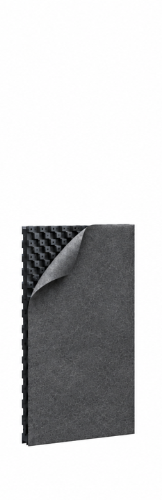
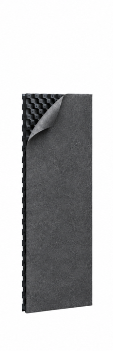
Flo-Wall® is available in a range of pre-assembled configurations for vertical drainage applications. Where project requirements call for a different drainage profile or performance characteristics, other Atlantis Flo-Cell® products, including 20mm, 30mm FLEX, 50mm and 52mm, can also be configured for wall drainage applications.
Part Number
Width
Height
Thickness
Part Weight
Vertical Flow Rate per panel*


Volume Void
Surface Void
Material
Colour
Chemical & Biological Resistance
Service Temperature
Approximate Material Lifespan
90%
70%
100% Recycled Materials, 95% Recycled Polypropylene 5% Propriety Selected Materials
Black
Excellent resistance to urine, acids, alcohols, bases and mineral oils. Good resistance to aldehydes, esters, aliphatic hydro-carbons, ketones and vegetable oils.
-100 C – 700 C ( 14 F0 – 158 F0 )
100 years + with no ultra violet exposure
*Panel is positioned vertically as per grpahics above with gravity flow. Hydraulic gradient (H.G) = 1.0.
Note: Atlantis® product specifications are updated on a regular basis. Please contact Atlantis® technical department for the latest data sheet available
Base Collection
Completing the Drainage Path
At the base of the wall, Atlantis Flo-Pipe® can be integrated with the vertical drainage system to collect water conveyed through the Flo-Wall® and direct it toward the project’s designated drainage or discharge point. Its low-profile linear configuration allows the collection pathway to be coordinated along the base of the retained structure.