Atlantis Modular Drainage Systems
Flo-Tank®
Compact modular polypropylene system for subsurface drainage and void-space applications, designed for integration into engineered landscape and stormwater assemblies.

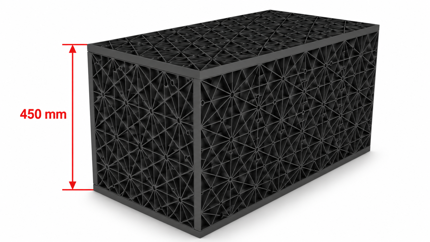
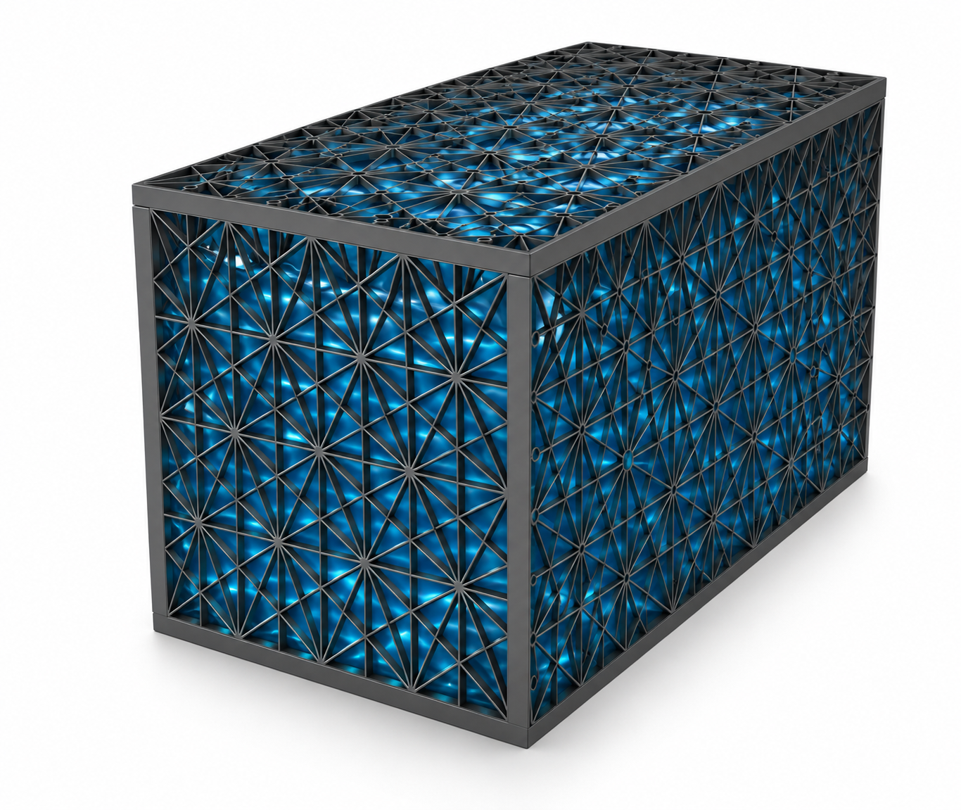
Atlantis Flo-Tank® is a modular geocellular system designed to collect, temporarily store and manage stormwater below ground. Its interconnected modules create a high-void underground structure that can be configured to accommodate different site conditions, storage requirements and stormwater management strategies.
Depending on the system configuration, Flo-Tank® can be incorporated into on-site detention, infiltration and rainwater harvesting applications, helping integrate stormwater infrastructure beneath landscaped areas, pedestrian surfaces and other developed spaces.
The modular design allows individual units to be assembled into underground storage structures of varying dimensions, providing flexibility for project-specific engineering requirements.
Product Design and Function
Interlocking Plate Assembly
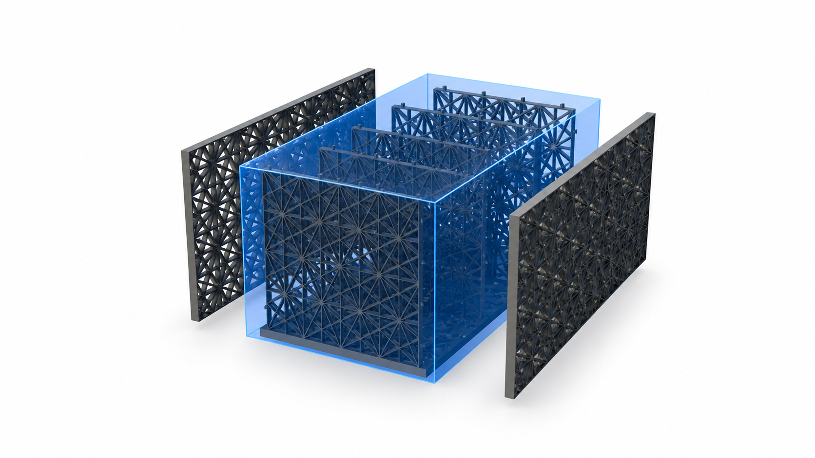
The Atlantis Flo-Tank® is constructed from individual polypropylene plates featuring an open-lattice geometry that allows water to enter and move freely through the structure.
These components interlock to form a three-dimensional modular unit, creating an interconnected internal void space for water storage and drainage. The assembly system enables individual plates to be connected into a complete, self-supporting module.
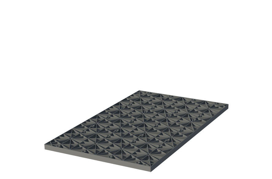
Large Plate forms the base of the module.
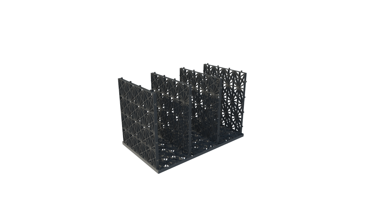
Small Plates installed vertically onto the base to form the internal structure.

Large Plates connected to the assembly to enclose the sides of the module.
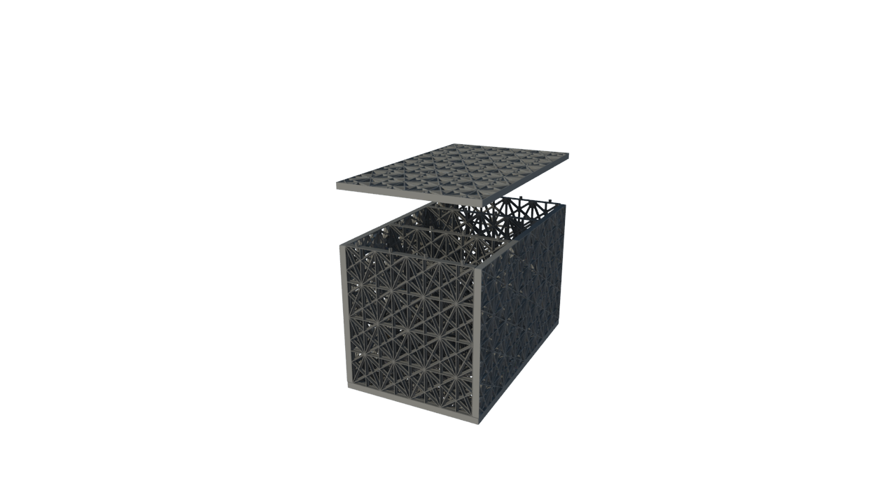
Large Plate secures the top of the assembly, completing the module enclosure.
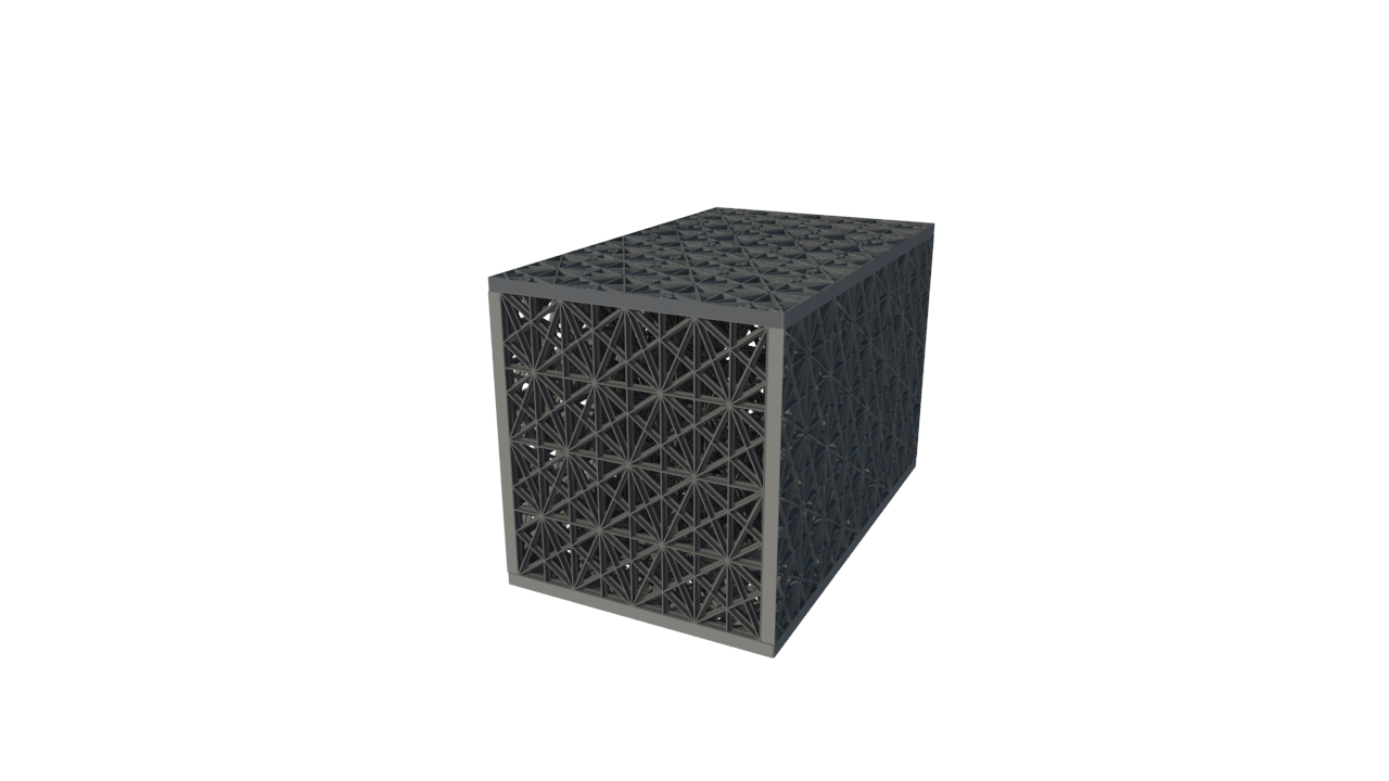
Flo-Tank® complete modular unit, ready for integration into the specified system.
Vertical Module Connection
Atlantis Flo-Tank® modules can be assembled vertically to create multi-level configurations, allowing the overall system depth to be adapted to project-specific requirements.
The top plate of each completed level also serves as the base plate for the level directly above. Additional internal and side plates are connected to this shared plate, extending the structure vertically without requiring a separate base plate for each level.
This assembly process can be repeated to achieve the required system depth, subject to the structural loading conditions and engineering requirements of the project.
A fully assembled Flo-Tank® forms the first level of the vertical structure.
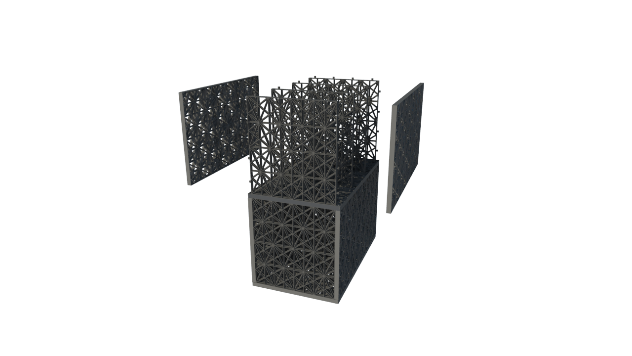
Small Plates are installed onto the existing top plate, which serves as the base for the next level.
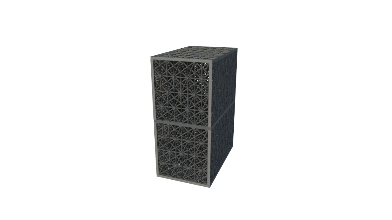
The second level is completed using the shared horizontal plate between both modules.
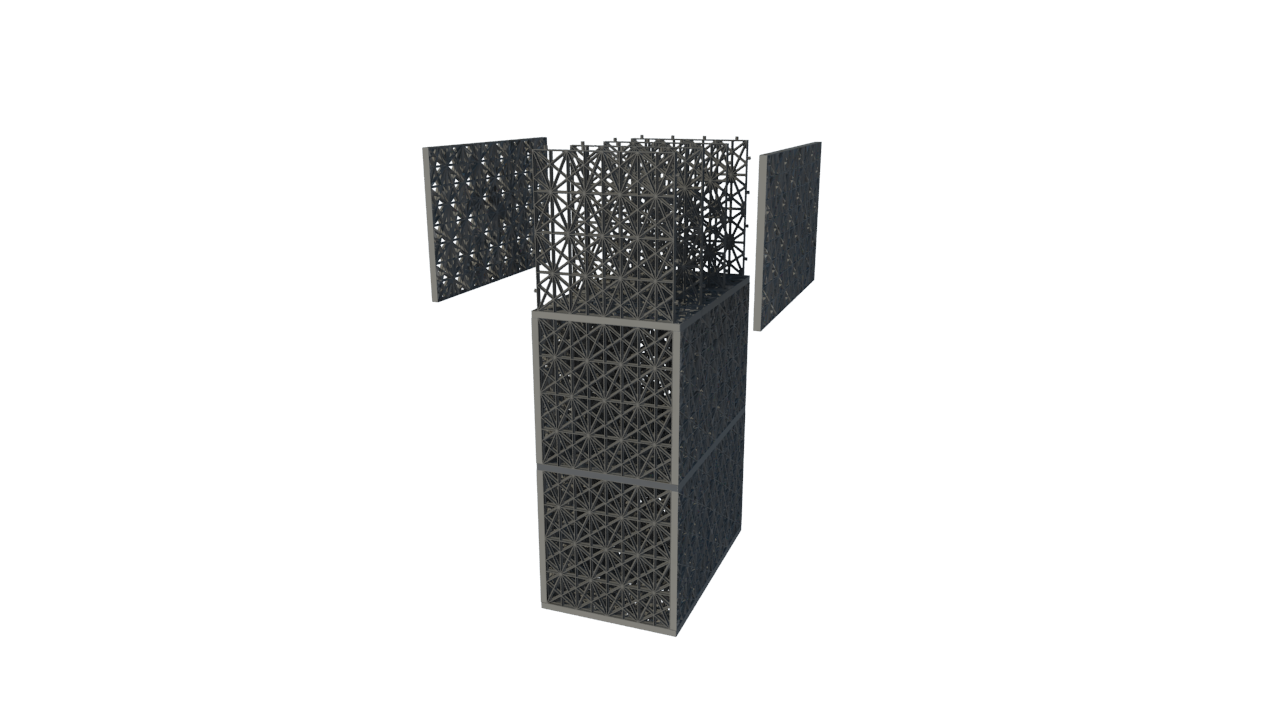
Additional internal and side plates extend the structure vertically to form another level.
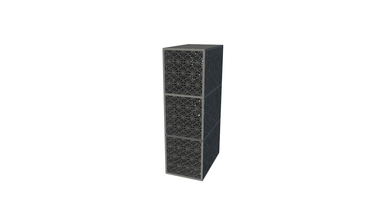
The completed structure demonstrates how successive levels can be interconnected to achieve greater system depth.
Internal Plate Configuration
The Flo-Tank® is available with different internal reinforcement configurations to accommodate varying structural loading requirements.
The standard configuration incorporates four internal plates, while five-plate and seven-plate configurations provide additional internal reinforcement to increase resistance to compressive loads.
The appropriate configuration is determined by the anticipated loading conditions and the structural requirements of the installation.
4 Plates
Standard configuration for applications with lower structural loading requirements.

5 Plates
Additional internal reinforcement for applications requiring increased compressive resistance.

7 Plates
Enhanced internal reinforcement for applications subject to higher compressive loads.
Technical Specifications
Part Number
Part Size
Gross Volume
Storage Capacity
Ultimate Strength
Flow Rate
Part Weight
Modules per m³ / ft³
Service Temperature
Volume Void
Material
Colour
Chemical & Biological Resistance
Approximate Material Lifespan
Applications & System Integration
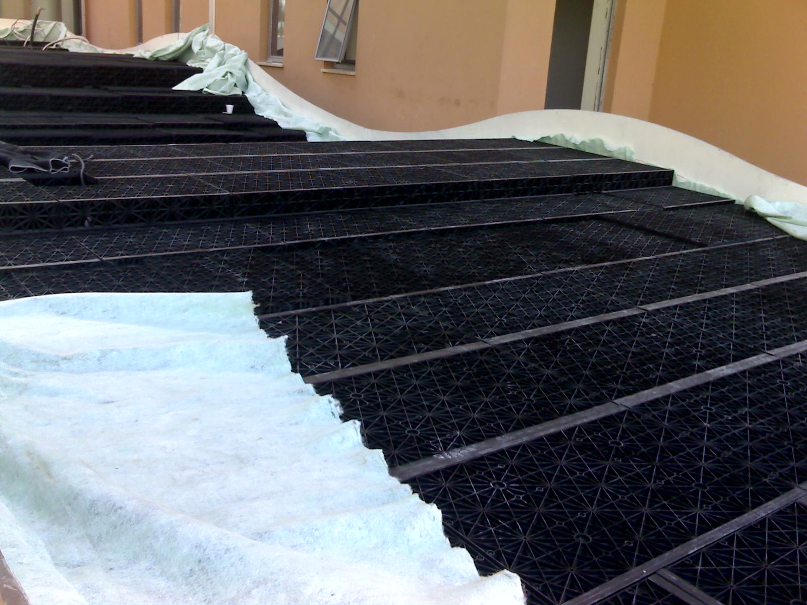
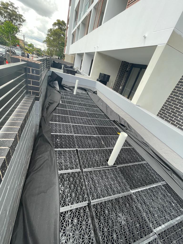
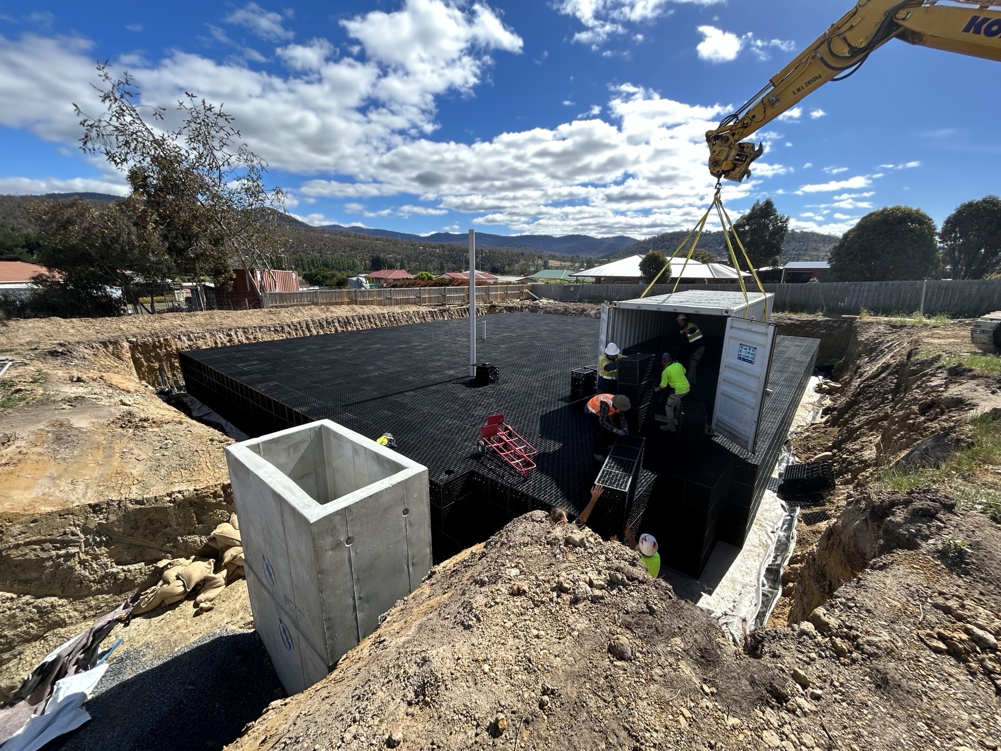
Flo-Tank® in Practice
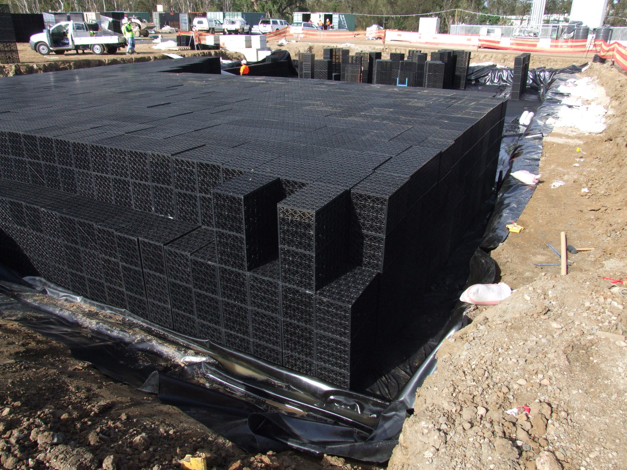
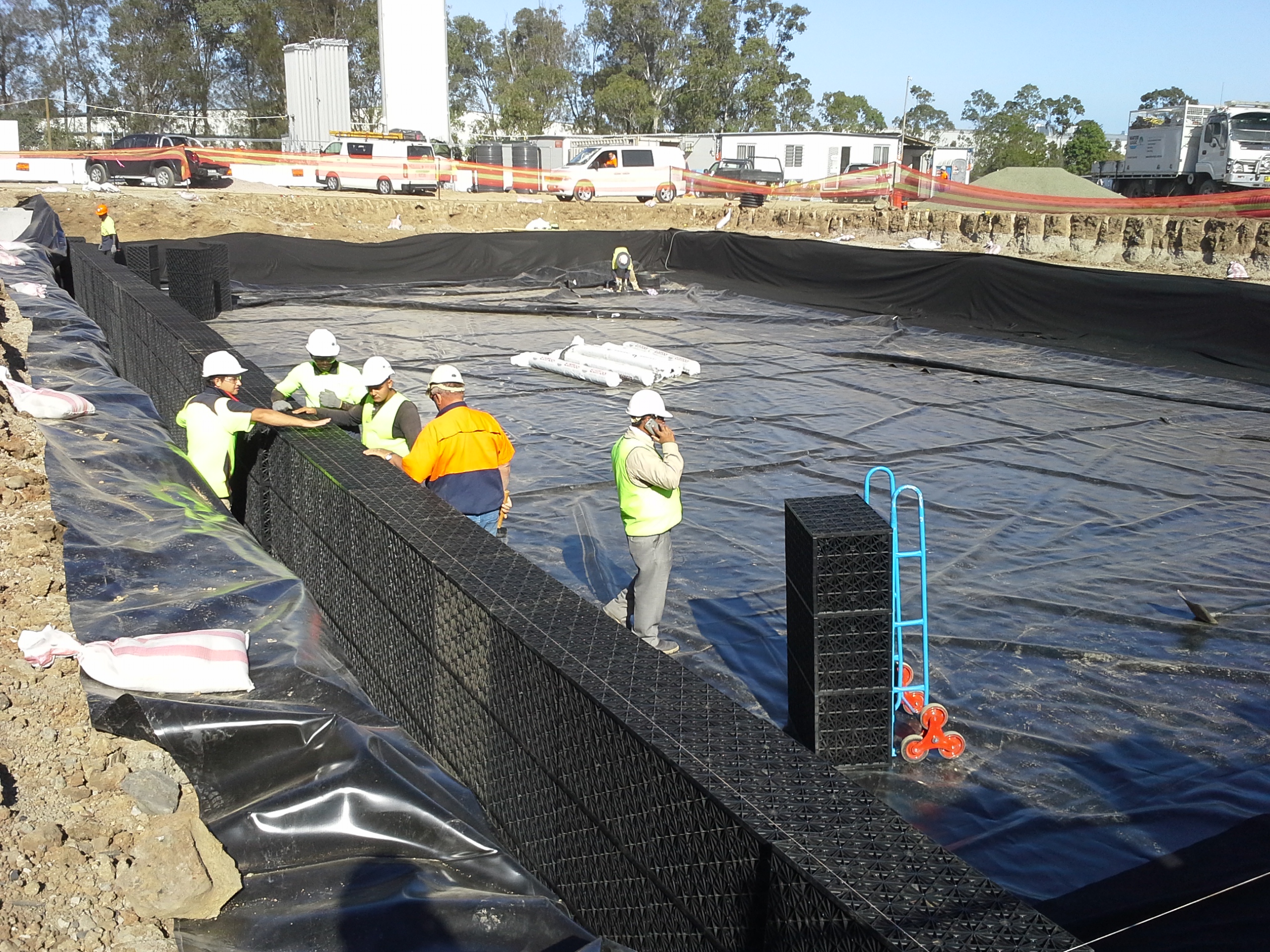
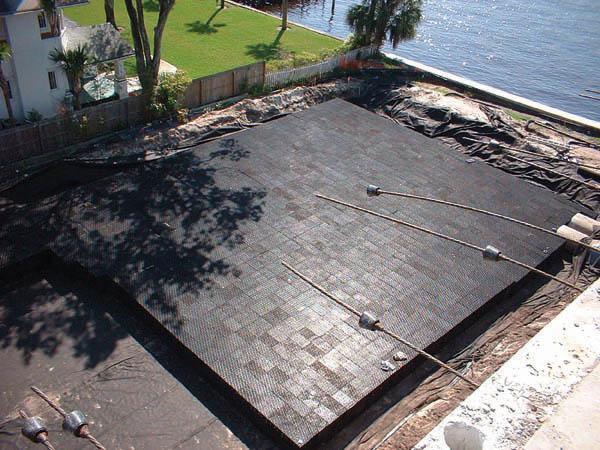
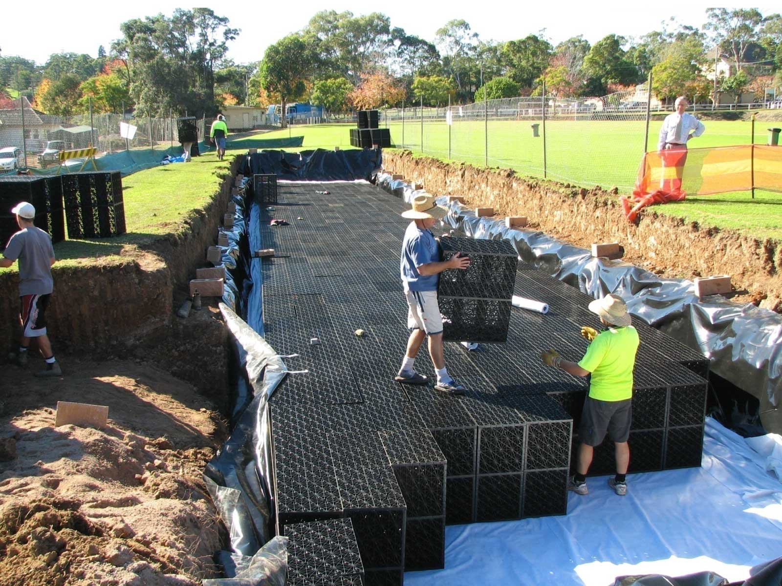
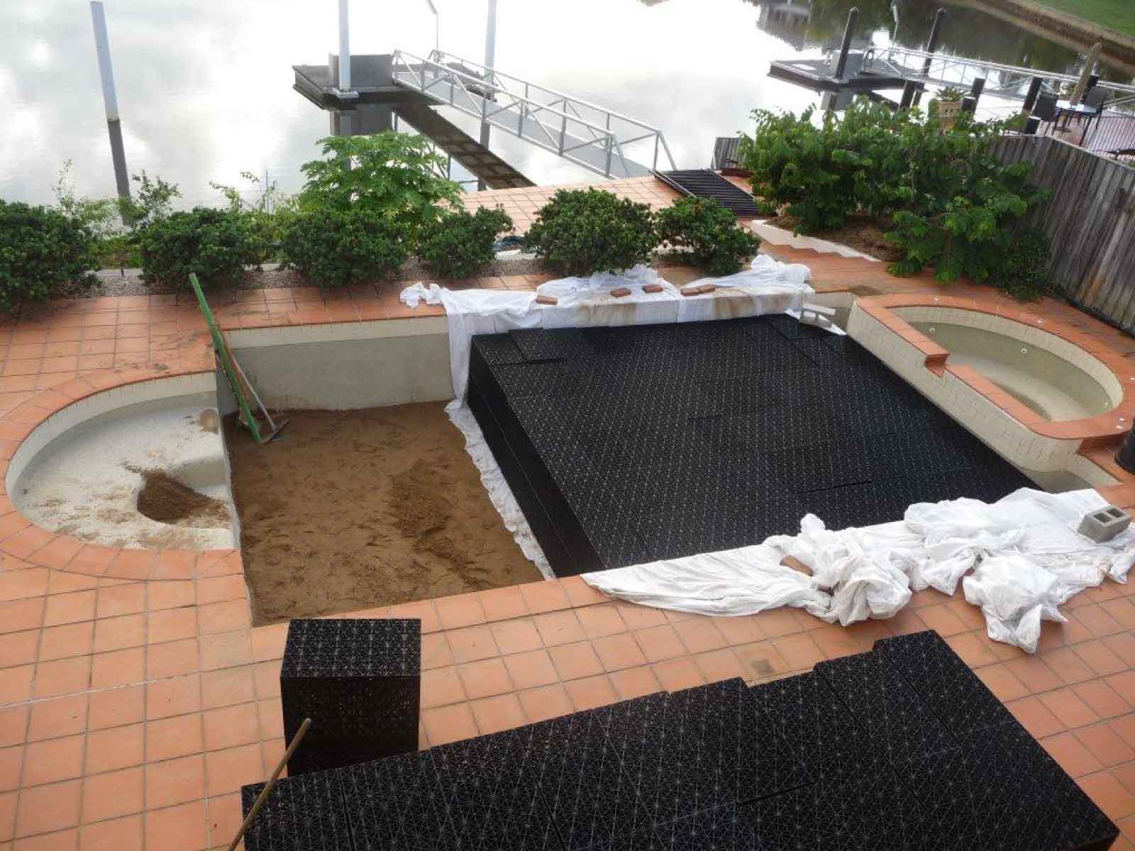
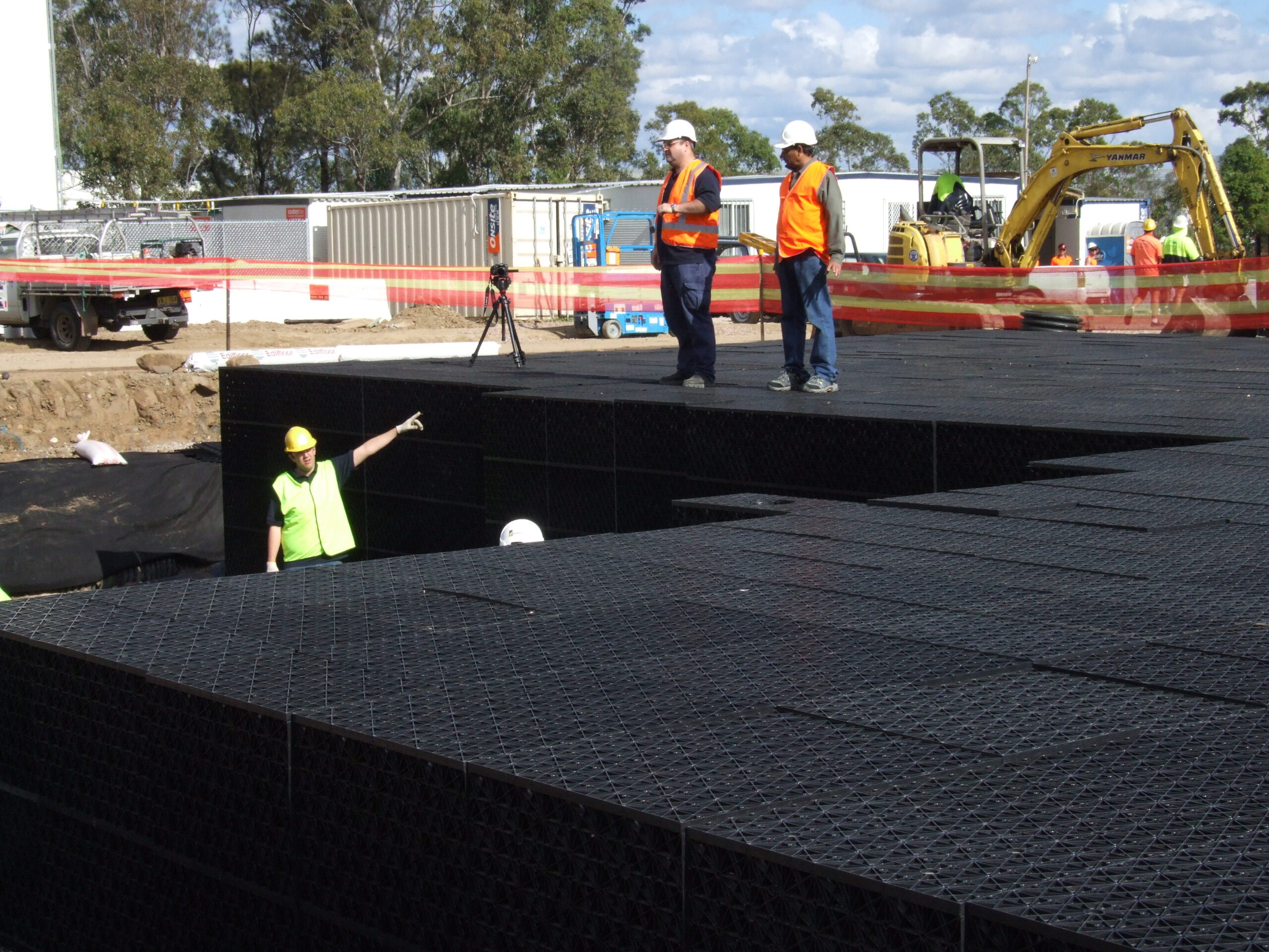
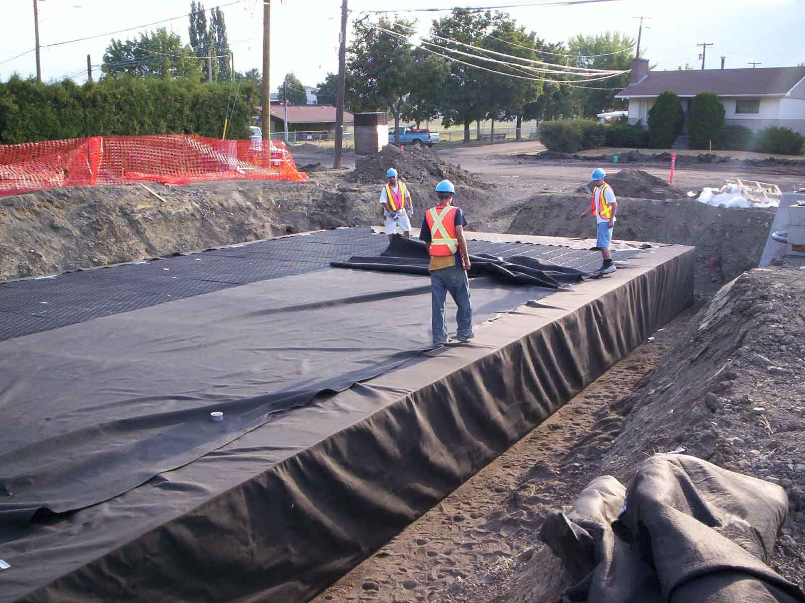
Explore how Atlantis Flo-Tank® modules have been incorporated into engineered landscape and subsurface applications. Project examples illustrate system configurations, site constraints and the integration of modular void-space solutions within the overall construction.